
Before we study the anatomy of the heart and great vessels in detail, it is important to understand their location, orientation, and surface anatomy as seen on CT (Computed Tomography) and MRI (Magentic Resonance Imaging).
Author
Dr Tarun K Mittal MD, FRCR, MSc, FSCCT
Consultant Cardiothoracic Radiologist
Royal Brompton and Harefield NHS Hospitals
Guy’s and St. Thomas’ NHS Foundation Trust
Senior Clinical Lecturer, Imperial College London
Location of Heart and Great Vessels
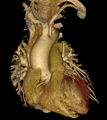
The heart is located in the middle mediastinum between the lungs surrounded by their pleura on either side, sternum anteriorly, and the thoracic spine posteriorly (Figure 1) (1). The heart is conical or pyramidal in shape with a base and an apex with the latter pointing laterally and inferiorly. Almost two-thirds of the heart lies on the left side of the sternum and it sits on the diaphragm, the left diaphragm is displaced inferiorly compared to the right (Video 1). The heart is surrounded by the pericardium except posteriorly at the drainage of the pulmonary veins and between latter and the superior and inferior vena cavae. The main pulmonary artery and the ascending aorta arises from the superior surface of the heart.[su_tooltip text=”4. Test reference” position=”right” background=”#5d738a”]4[/su_tooltip]
Cardiac base, apex, and axis
As the heart is pyramidal in shape, it can be considered to have a base which is formed by the posterior surface of the left atrium located posteriorly facing the spine and an apex, formed by the apex of the left ventricle. Due to the particular shape of the heart and orientation, any cardiac imaging is best performed in a plane along the axis of the heart (from the base to apex) and thus called the long-axis views, or planes perpendicular to the long-axis called the short-axis views. However, the heart can be studied on standard anatomic axial, coronal, and sagittal views as well as oblique views. We will learn more about the cardiac long- and short-axis views later on.
1. Abbara S, Blanke P, Maroules CD, Cheezum M, Choi AD, Han BK, et al. SCCT guidelines for the performance and acquisition of coronary computed tomographic angiography: A report of the society of Cardiovascular Computed Tomography Guidelines Committee: Endorsed by the North American Society for Cardiovascular Imaging (NASCI). J Cardiovasc Comput Tomogr. 2016;10(6):435-49.
2. Pelberg R, Budoff M, Goraya T, Keevil J, Lesser J, Litwin S, et al. Training, competency, and certification in cardiac CT: a summary statement from the Society of Cardiovascular Computed Tomography. J Cardiovasc Comput Tomogr. 2011;5(5):279-85.
3. Hounsfield GN. Computed Medical Imaging, Noble Lecture 1979 [Available from: https://www.nobelprize.org/prizes/medicine/1979/hounsfield/lecture/.
4. Hausleiter J, Meyer T, Hermann F, Hadamitzky M, Krebs M, Gerber TC, et al. Estimated radiation dose associated with cardiac CT angiography. JAMA. 2009;301(5):500-7.
5. Zanzonico P, Dauer L, Strauss HW. Radiobiology in Cardiovascular Imaging. JACC Cardiovasc Imaging. 2016;9(12):1446-61.
Figure 1: View of a modern MDCT scanner with scanner gantry, scanner bore, and ECG monitor (a). Patient lying on the table with ECG-leads placed on the chest (b) and arms raised and resting behind on a support (a).
Figure 2: (a) Showing inside of the MDCT scanner with the x-ray tube at one end and row of detector array at the opposite end. (b) Schematic of a detector array with multiple detector rows (each of 0.5 or 0.6 mm width) constituting the entire width of the detector in Z-direction (up to 16 cm). Each detector row is made of hundreds of small elements.
Figure 3: (a) Volume rendered cardiac CT angiography image showing the whole heart with length of 12-14 cm and (b) showing presence of multiple ‘step artefacts’ (white arrows).